What is a Single-Pair Power Over Ethernet?
Operational Technology (OT) devices require both data and power to perform their target functions. Power is not always available at the device’s installed location. Further, battery-powered installations create significant maintenance and reliability issues.
Single-pair Power over Ethernet (SPoE), like traditional PoE solves these problems by providing power over the existing data cabling. SPoE enables remote placement of end devices, liberating installations from the expense and hassle of local device power. SPoE builds on traditional PoE and can be easily installed and maintained. SPoE-compliant switches and endpoints ensure network additions and upgrades are simple and fast.
Key Benefits:
- Standards-based interoperability
- Ease of installation
- Power and data over single pair
- SPoE provides between 1.23W and 52W, depending on output voltage, cable length and power demand
- Enables resilient power architectures
- LPS/SELV/NEC Class 2
Single-Pair Power Over Ethernet Overview
IEEE 802.3 originally standardized powering over a single pair of conductors at 100Mb/s and 1000Mb/s in IEEE 802.3bu, known as Power over Data Lines (PoDL). IEEE 802.3cg extended the specification to support 10Mb/s for OT environments. In practice there are two variants of single-pair powering, SPoE and PoDL.
SPoE is used to describe the classification-based implementation utilized in OT networks while PoDL is used in engineered networks, e.g., in-car networks.


SPoE Key Characteristics:
SPoE deploys the following key tactics.
1. Full voltage is not applied unless a PD is connected
2. Full voltage is removed quickly when the PD is disconnected
3. Full voltage is removed very quickly in the event of a fault (e.g., short-circuit)
Prior to the application of power, a short exchange of information takes place between the power source (the PSE) and the power load (the PD). This process is known as classification and allows PSEs and PDs to determine if their voltage and power requirements are mutually compatible. Multiple voltage and power levels are defined in IEEE 802.3.

Low power standby requirements apply to many OT markets and applications. Government and industry mandated standby requirements have steadily become more rigorous and will continue to do so. SPoE enables multiple levels of low power standby modes to ensure standby requirements can be met both today and in the future.
SPoE Key Capabilities
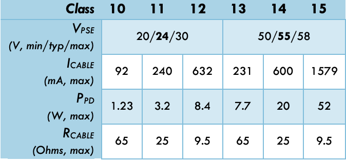
Today, OT deployments often use a 24V DC supply voltage. However, power delivery on long cables at this voltage is subject to significant losses due to cable resistance. Power delivery efficiency is maximized when the voltage is raised near the SELV maximum, 60V DC. As shown below, SPoE provides two distinct operating voltages: 24V and 55V DC.
Six unique classes are defined for OT networks. Classes 10, 11, and 12 enable 24V DC power delivery over long, medium, and short cables respectively. Likewise, Classes 13, 14, and 15 enable 54V DC power delivery over long, medium, and short cables respectively.
Why We Are One
For over 40 years, IBS Electronics Group has provided a broad range of integrated supply chain and electronicsmanufacturing solutions tailored specific to our customer's operations. As your one source for the industry’s top brands all in one place, our engineers specialize in reducing supply chain complexity and are here to provide you with dedicated support from prototype to production.


.png)


.png?resizemode=force&maxsidesize=96)